|
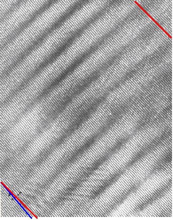
The HRTEM picture shows sets
of {111} lattice planes for a tilt boundary on {111}. There are
three sets of screw dislocations, but only one set can be seen. |
|
 |
The left picture is an overview. The small angle
grain boundary is inclined (it is essentially contained between the two red
lines); to the far left or right just one of the two grain is seen. |
|
|
Depending on the local thickness of the grains in
the area where they overlap, grain one or grain two dominates the picture.
|
|
|
|
|
|
Traces of the two grains are marked in red and blue; the red
trace has been shifted to show the twist angle (and the extension of the
boundary). |
|
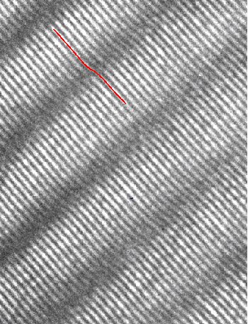
The enlargement with a tracing of a {111} plane shows
the effect of the screw dislocation. |
|
|
|
|
|
|
|
|
|
|
|
|
|
© H. Föll