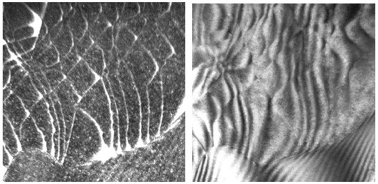
| The two pictures below show the extremes in resolution. | |||
| On the left hand side is a weak beam image of a dislocation network in a small angle grain boundary in Si; it has optimum resolution. The dislocation end at a SiO2 precipitate which shows faint fringes due to Moirée effects (the Si precipitate is sandwiched between Si crystals which are slightly misoriented). | |||
| On the right hand side is the same area imaged with (rather dynamical) bright field conditions. The dislocation lines are very broad and their images interfere with each other; it would be difficult to interpret this picture. | |||
|
|||
![]() 6.3.2 Examples and Case Studies for Dislocations
6.3.2 Examples and Case Studies for Dislocations
© H. Föll